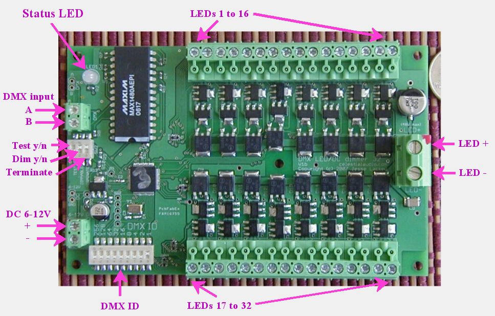
32 channel DMX dimmer pack for LEDs (or anything DC powered)
PLEASE NOTE: this has been replaced by a Version 2
This
board is for sale!
Board size: 5.5" x 3.5", with 5 holes for 6-32 screws; a set of 5 1/4"
standoffs are provided. There are
4 holes at the corners and one near the middle, at 3.325" x 1.7"
relative to lower left corner.
Top view:

Feature set:
- 32 channels with one
small board! No more compromises due
to not having as many channels as you really want.
- Each channel can switch 4 Amps,
total
current capability of the board is 30A
continuous.
- Each channel can switch up to 48V
for driving large clusters of
LEDs efficiently.
- Each channel diode protected from inductive load switching spikes.
- Fully isolated DMX input,
using the marvelous and not cheap
Maxim MAX1480 isolated RS-485 transceiver.
- 256 levels of dimming with smaller "steps" at the dimmest levels
(effectively 10-bit) at a pulse-width-modulation (PWM) refresh
rate of 125Hz. This
allows smooth fade up & down from black with no flicker
ever!
- LED brightness levels retained if DMX signal is lost.
- DMX start channel (1-511) set via DIP switch, changes are
immediate, status LED blinks orange to acknowledge
setting change.
- DMX termination on/off via DIP switch. No jumpers or plugs
to deal with!
- Dimming enabled on all channels yes/no via DIP switch to protect
non-dimmable equipment
from damage.
- Run test chase pattern yes/no via DIP switch - very handy
for
debugging installations.
- Supports the top speed possible with DMX: 512 channel frames @
44fps. No having to set a max fps rate, or a delay between
frames, or any other hacks some other DMX devices require.
- Multicolor status LED indicates DMX protocol or wiring error
(red), no DMX wire connected / no data on connection
(green slow blink), and valid DMX frames incoming (green fast blink)
- LED connection headers are a unique "pluggable" design: they can
be unplugged
from the board, wires added/removed, then plugged back in. They
can be plugged in two ways: such that the wires exit parallel to the
board, the conventional case (shown in picture) or straight up out of
the
board. This allows for much easier installation and for moving
installations, since the board and the LED clusters are easily
separated.
- Board electronics runs from 6-12V DC @ 150mA, reverse polarity
protected. 5V powering
possible with caveats; ask for details if this would be beneficial to
your application.
- The DMX and DC power input have plated input holes on the board
(as well as terminal blocks) to allow wires to be directly soldered to
the board if desired.
- Up to 16 boards can run from a single DMX source, so a complete
DMX
universe of 512 high-current channels can be easily built.
Since this board is intended to be installed in an enclosure with other
equipment, and wiring requirements are highly dependent on the
installation, there is
no case provided and the DMX connection is with a terminal block
instead
of a bulky 3 or 5-pin XLR. See
wiring diagram below for details.
This design is a significant revision of a client project that has been working
well
for years, but now physically smaller, less expensive to produce, and
90% faster PWM refresh rate.
The basic operation is that this board switches the negative of your LED clusters to
the LED power supply's ground. This is called low-side switching,
and is the most common way things like this are done, since it is
simpler, cheaper, and a little more efficient than switching the
positive of the LED clusters (called high-side switching).
The wiring diagram is here.
Some notes about the wiring:
- LED cluster positives are all tied together with thick wire (up
to 30A continuous) to the positive of the power supply for the LEDs (up
to 48V).
- LED cluster negative goes to terminal block. This can be a
thinner wire, since only the current for that cluster goes down it (up
to 4A).
- LED power supply goes to LED power terminal block (the large one
on the right). The positive can be a thin wire, this is only used
for the diode inductive switching protection. The negative needs
to be a thick wire, since the current for all the clusters goes through this
wire (up to 30A continuous).
- This board doesn't do any current limiting. When it
switches a cluster on (i.e. the cluster's negative is switched to
ground) the effective resistance of that switch is less than a tenth of an ohm. Therefore
the LED cluster has to be designed to limit current to whatever the
LEDs are rated for, up to 4 amps (this board's per-channel
maximum). A good test of a cluster is to connect it to the LED
power supply directly and measure resulting current. I am happy
to advise on LED cluster designs.
PLEASE NOTE: this has been replaced by a Version 2
DMX LED Home
Celestial Audio Home
