bm2006: 16 RGB LEDs, 9V powered wearable unit that can run
standalone or with DMX
This web page documents a board with 16 RGB LEDs
Board size: 3.00 x 3.00 two-layer, with slick black soldermask
Project timeframe: August 2006
Client: Leo Villareal
Webpage created: May 20 2007
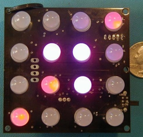
Top view:
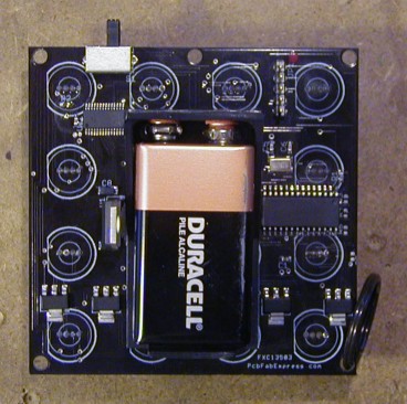
Bottom view:
bm2006 (i.e. the blinky for
Burningman 2006) is the latest and possibly final in the series of
wearable LED
blinkies for Leo Villareal / disorient.
(previous years: bm2005, bm2004). bm2006 is a grid of 16
10mm RGB LEDs, and is actually
two design variations on one board: standalone pattern synthesis, and
RS-485 controllable with either a custom protocol or DMX.
I did the "architectural" design of both the hardware and software -
describing the hardware design and writing the core software that runs
everything. Todd Polenberg did the hardware layout, handled the
manufacturing, and wrote the pattern synthesis part of the software
with my occasional consultation. The hardware layout is a bit of
a trick, while the board isn't particularly dense, the LEDs are 4-pin
through-hole and on a perfectly regular grid, and the electronics are
as SMT as possible and are all on the backside, placed between and
around the LED pin pads. Glad I made Todd do it. :)
The design has three major parts: a TI TLC5940 16 channel PWM LED
driver, four PFETs for a 4-way mux, and a PIC18F252 to run the
show. The PIC software is in C using the CCS C compiler.
The board can be built with a 9V holder (shown above) for wearing, or
with a 4-pin header for power/gnd/RS-485 and a standard 75176 8-pin
SOIC RS-485 transceiver.
The TLC5940
is a very handly little chip. While PWM can be done
in software (32 channels of 8-bit here),
this design needed 48 channels and to be able to drive the LEDs at
about 60mA - so the PIC can't sink the current thru a pin (current
limit for PIC i/o is a quite reasonable 25mA). By doing a 4-way
mux of the 16 LED driver chip we could achieve these goals with minimal
parts and hassle. Note: since the LED driver chip is 16 channels,
and we have 16 LEDs of 3 colors, why didn't we just do a 3-way
mux? Well, that was the original plan, but the layout was going
to be somewhere between arduous and impossible on a 2-layer
board. So for an extra 30c we did it 4-way.
There are some difficulties with the TI chip. For starters, it
doesn't just "auto run". It is 12-bit, and after sending it 4096
clocks, you have to toggle a pin to reset the PWM counter. This
is required, and is a serious design hassle. Additionally, it
seems in our usage anyway, that new PWM settings have to be loaded in
while the PWM clock is stopped. There may be something I'm doing
wrong, but considerable effort was spent with no luck. So this
means when doing multiplexing, where new PWM data is loaded each
multiplex step, that all the LEDs are off while the data is being
loaded. This makes the display more susceptible to flickering and
the overall output dimmer. However, for this design low power is
essential for battery operation for reasonable runtimes, so everything
is being run fairly dimly anyway. Flicker was not a problem at
all.
For dealing with the PWM counter: the PIC generates the PWM clock via
one of its hardware PWM generators running at maximum speed
(5Mhz). This goes to the TI chip and the input pin for one of the
PICs counters. When the counter hits 4096, the PWM generator is
turned off, new PWM data for the new mux phase is loaded into the TI
chip, the TI chip's PWM cycle is reset, the pfet for the mux step is
turned on, and then the PIC PWM hardware is activated again and repeat.
The RS-485 version hasn't been used much (at least not yet), but was
essential for making a 3x3 grid of these units, to form a DMX-enabled
prototype of this beast.
These also make excellent "taillights" for bicycle riding at night in
Oakland. Of course, being Oakland, you can't leave it on your
bike while you're at the bar... :)
Home