No job too smallish or sillyish...
This web page documents a plethora of smaller designs and hacks, some
(ok almost all) with no commercial use, just for fun.
Last webpage update: May 29 2007
There's a lot of
stuff to document. They'll be more here as time and inspiration
strikes. Ya should see the pile of old circuit boards from old
projects I've got in a bin.
Webpage contents:
Midi-controlled
EL wire controller with dimming!
Timeframe: early 2002.
EL wire is great stuff; flexible, cool to the touch, glows in pretty
colors. I first saw it at Burningman in 1999. I knew what I
wanted to create: a MIDI controllable EL wire sequencer. This was
well before sequencer kits were available, and it was a royal PITA to
work with the stuff, etc. Yep I was like way hip back then.
Ok on to the technology. I was just getting into microcontrollers
again after several years, and PIC seemed to be all the rage.
The first thing was to figure out how to control it
electronically. EL wire uses an "inverter" to generate around
180V pseudo-AC (at 1Khz or more) from a DC supply; is the the electric
field the AC creates that charges up the electroluminescent material in
the "wire" that glows. So, to control the "wire", you've gotta
control this >1Khz, 180V pseudo-AC.
Just the thing for a beefy-ish triac. Triacs are designed to
control AC power, but they work fine with this EL wire "AC".
And, for bonus points, I added some simple dimming control, whereby the
triac is turned on and off rapidly in a PWM manner to give the illusion
of dimmer wire. However the way I did this was simple (no
zero-crossing detector) so there are only 8? 10? levels of dimming (I
forget). The MIDI velocity was mapped into the dimming levels.
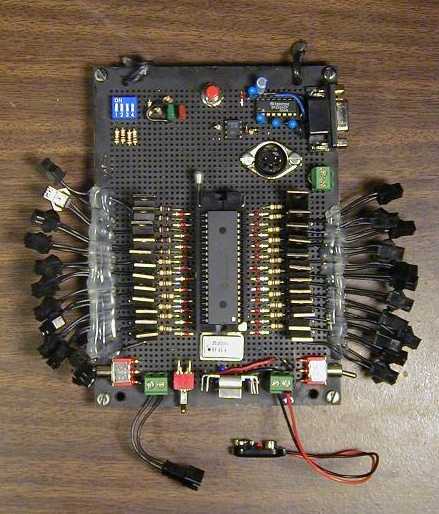
The board controls 24 strands of EL connected thru these handy
connectors Coolight has (or
had; this was 5 years ago). The board had a DIP switch to set
various test modes and RS-232 input as well. To help with
debugging, each of the 24 outputs had a little LED to show when it was
on.
So we've got MIDI message recieve parsing & 24 channels of PWM on a
PIC16F877 all written in assembler! No schematic, and no board
layout, this was prior to purchasing Eagle.
But if you'd like to look at the code... its here.
It took about 30 hours to hand-solder the board in perfboard.
And, I built two of them! Crazy kid!
What was nice about the whole design is that since it is MIDI
controlled, one could "play" it with a MIDI keyboard, and if the
keyboard was velocity-sensitive, the harder you hit a key, the brighter
the wire for that key glowed. And it was sequencable by any midi
sequencer; I used my laptop (RIP...) to run it at parties.
Because of the modular connectors, I could put different colors /
lengths of wire on each output as needed. And if that wasn't
enough, by getting some 3/4" metal pipe and various right-angle and
straight joins, I could screw together a frame to hold a cargo net that I then used to hold
the EL in whatever shape. Portable(ish) and fully
customizable. Action photos below.
Board front:
 and back:
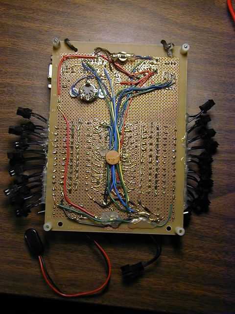
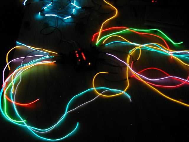
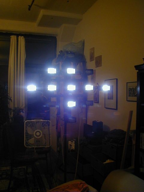
Front, lit up:
Party somewhere in Williamsburg bklyn may 2002, blurry b/c light level
low and it was rapidly animating:

And at the big burningman decompression party 2002, I believe it was:
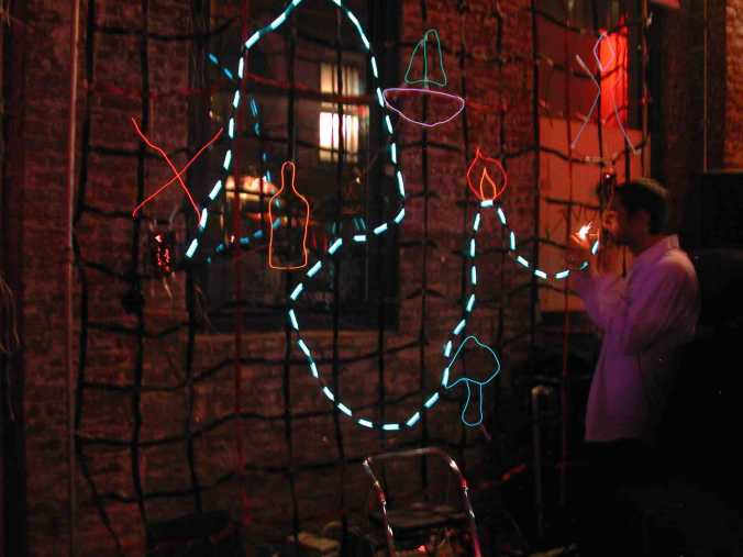
pls. excuse the um cigarette being lit... :) p.s. that's not me. I have
considerably thinner hair. :)
Midi controlled strobe light sculpture!
Timeframe: mid 2002
This project was born out of some research done (my very first client
EE project!) for Leo Villareal. He was trying to find a way to
put 640 computer-controlled strobe lights on the side of a building;
he'd been using these $20 generic cheapies for other projects, but we
needed precise triggering so patterns of flashes could be played out in
the installation. Due to the fact that these would have required
$60,000 worth of union-installed AC in conduit, low-voltage LED "strobe
lights" were eventually used instead. (Picture here).
Well the investigation was a success, in that precise control
could be attained by hacking these strobe lights. So, I built my
own little $100 creation. It takes Midi in from a
keyboard, and the lower half of the keyboard makes one of the 13
strobes flash just
once per keypress, and the upper half of the keyboard makes them flash
full speed for as long as the key is held down. You can press a
single key to all thirteen, and flash flash they go. I bought
some colored
plasic boxes from one of those places on Canal St. (manhattan) and
created a hanging thing with just the tops as "gels" to make it
colorful. And, the keyboard of course makes sounds too. So
we got tactile to sound & flashing bright colored lights that go
clack clack clack as they fire! (since they are real xenon and
stuff.). Party fun!
Final form:
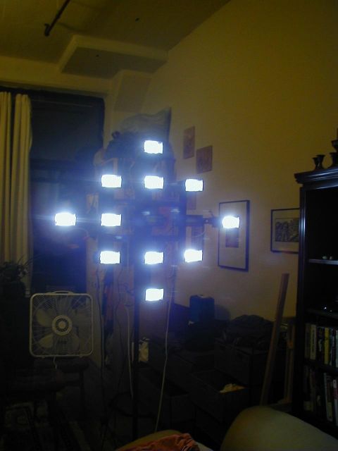
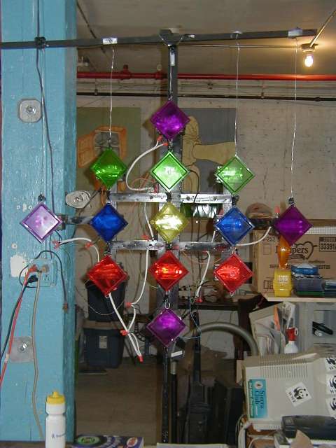 ...and without "gels":
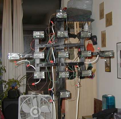
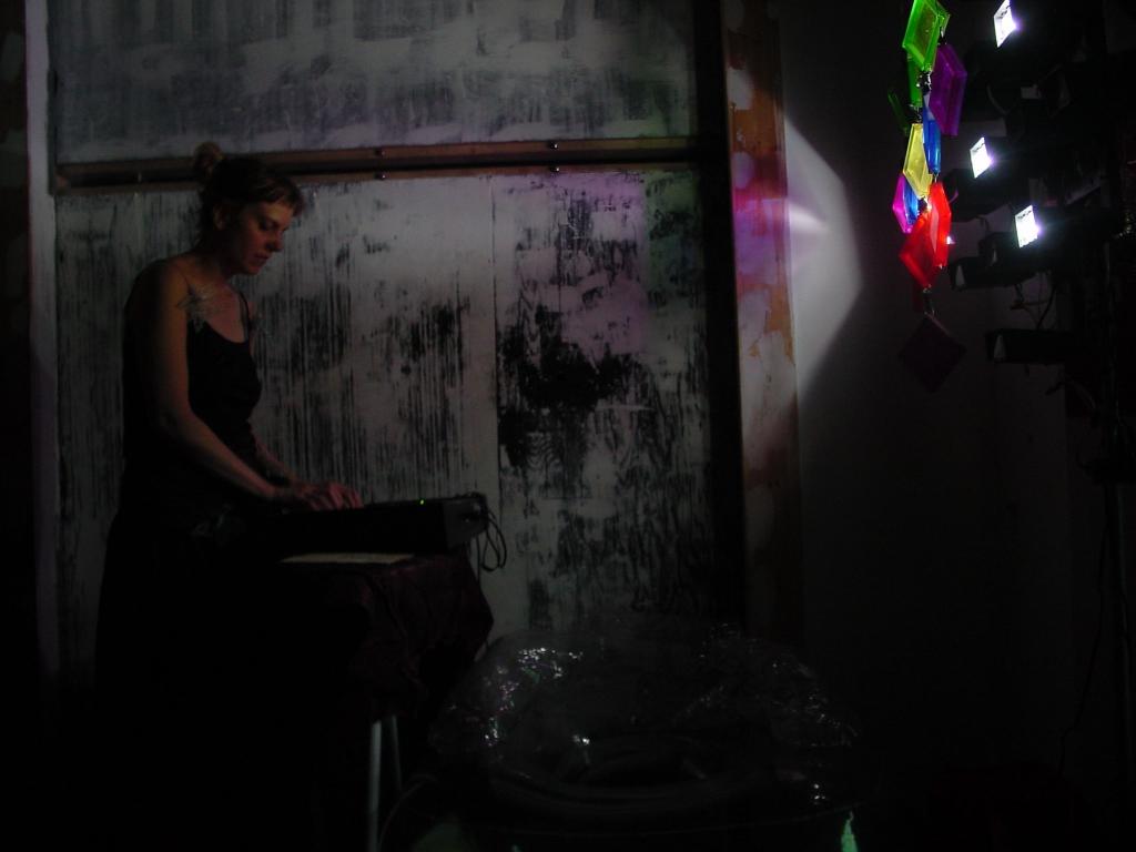
Party action! By pressing different key combinations (like visual
"chords") one can make different color patterns and shapes.
Two shots of it running w/o "gels":
Ok, in order to keep the size of this webpage down image-wise I'll put
the rest as links. The way the hack works is to to hold off the
trigger coil in the strobe light from charging. This is done by a
garden-variety opto-isolated triac. The timing of how long the
turn on the triac is somewhat critical; too short, and sometimes you
don't get a flash. Too long and sometimes you get a
double-flash. I tweaked it so that one gets a single flash at
least 99% of the time. Pic of that board is here. Sorry I don't have a
schematic.
The control board is a pretty simple thing - MIDI in, parsed, do timing
for a single flash. The opto-isolated triacs look like a LED
electrically; in fact, it is a little LED in them that triggers
them. So this is basically MIDI to a moderately precisely timed
LED flash. In assembler! Bah! On a home-etched board,
double Bah! Crazy kid. Board layout (png), Schematic (png), Eagle format schematic, board,
PIC16F assembler. DISCLAIMER: I
got all this working well; it even survived the playa, tho it definitely needs
some TLC now. However, all this was 5 years ago, and though I
believe this was the final working design, there are no
guarantees...
World's
smallest 8-output dmx/RS-485 "fanout" board!
Timeframe: May 2005
Sometimes size really does matter. In this case, what was needed
was a way to "split" a DMX signal to feed 8 separate sets of 16? DMX
inputs wired in parallel. No big deal, but it had to go inside a
smallish box, that was sized to be hidden by the infrastructure in a
large LED installation. Inside this box was a super-beefy 5V
power supply running... 64 I think it was LED "strobe lights", check it
out here: video.
Anyway, so there was no space, and the 5V was extremely
dirty, since it was going from heavily loaded to virtually nothing
rapidly and constantly. So, what to do? Well, I looked
around for 3.3V RS-485 parts. There are some, but no multi-output
ones, at least not at the time. Designing a DC/DC to boost from
dirty 5V to 7V and then LDO it to get a clean 5V was a possibility
but... it would take up more space and be a considerable number of
parts. So I did a little trick. Take your dirty 5V, put it
thru a diode to a big cap. Now you have a "peak detector" power
supply. The cap charges to ~4.75V (5V minus the Vf of the diode)
when the load is light. When the load goes way up and the supply
sags a little, no problem - the diode prevents the cap from discharging
to the no-longer-5V supply. To get the lowest Vf, I took three
diodes with particularly good Vf and put 'em in parallel. So the
supply is a fairly clean 4.75V, thereabouts. This is within spec
for 5V RS-485 parts. There were... 4? of these? 6? I
forget. Anyway its been running for years. There's even a
little power-good LED and "fault" LED if the RS-485 is backwards or one
or both lines are shorted or open, to help stressed-out
wire-installers (racing to finish it all before the gala
opening) debug any problems.
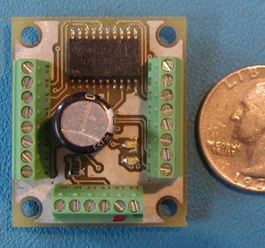
Top of board:
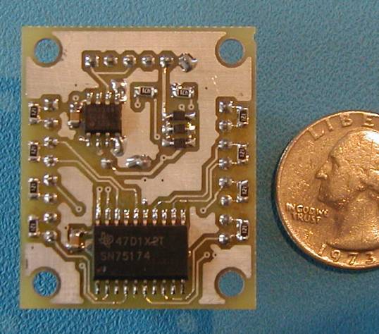
...and the bottom:
Home