Portable four channel mic preamp and
A/D
converter with matched gains for surround sound recording
This web page documents the development of this unit. This is a
commercial product, development nearly completed.
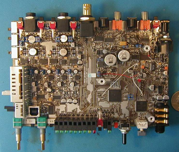
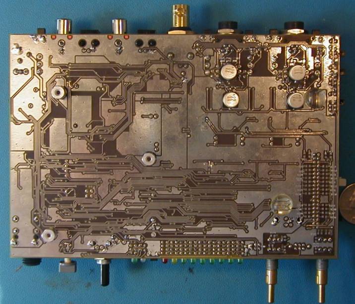
Board is 4-layer 6.75" x 4.6"
Design timeframe: Early 2006 to present
Last webpage update: May 18, 2007
Top View:

Bottom View:

This product was developed
specifically for a new microphone with 4 capsules, designed
for portable,
affordable, surround sound recording. In order to make this
possible, two important features are needed.
- The mic preamp gains per channel need to be tightly matched;
+-0.1db or better. This is not a standard feature on 4 channel
preamps, since for all conventional uses gain matching is not required.
- A means to losslessly encode 4 audio streams into 2, to enable
recording by a common 2 channel digital recorder, thereby avoiding
having to purchase an expensive, specialty 4 channel digital recorder.
4ch has a number of other
features, listed briefly below.
- Variable and fixed gain settings, 0 to 60db
- 9 steps of LED signal monitoring for each channel
- Flexible headphone monitoring - 7 modes
- Complete set of sample rates, from 32kHz to 192kHz
- Sync to external SPDIF in
- 48V phantom power (on/off switchable per channel) capable of
full-spec 10mA on each
of the 4 channels simultaneously
- Runs on two standard 9V batteries (hot swappable) or DC input
- Firmware updateable via USB
Design Overview
The design was dictated by two overriding factors: the gain matching
and running for 4+ hours on two standard 9V alkaline batteries.
Various power-saving design features were implemented, including
multiple dc/dc converters, shutdown of unused chips when possible,
selection of the newer versions of "classic" audio chips and Toslink
transmitters, LED display on/off switch, headphone shutdown, and
the like. Gain matching is done by using popular pro-audio
instrumentation amps, with gain set by a switch that selects between a
series of fixed gain steps (selected by another slide switch), variable
gain
via 2 dual-shaft pots, or line-level.
How are 4 channels converted losslessly
into a single stereo pair? Multiplexing. Consider this: 4
channels of 48KHz/24bit audio can be sent down a 2 channel 96KHz/24bit
line using some bit-swizzling magic. Channel 1 of the 48KHz
stream becomes the "Left" in the 96KHz stream, channel 2 becomes the
"Right", channel 3 becomes the next "Left", channel 4 the next
"Right". Since 96KHz is running 2x the speed of 48KHz, everything
is synchronized and no samples nor bits are dropped. The 96KHz
"stereo" recording is not playable or monitor-able as is, since the
left and right channels are each actually two channels switching back
and forth sample by sample, but a simple utility application splits the
recording back out
into the 4 separate tracks. Since the generic 2-track,
96KHz recorder can't monitor this multiplexed stream this unit has
flexible
meters and monitoring.
Major design blocks
Handling 4 streams of 24bit, up to 192KHz serially, with a variety of
clocks to create, flexible signal routing, and sample-by-sample
analysis for the LED meters is a job microcontrollers are not well
suited for. Instead of using an expensive, power-hungry 32bit
(something) with a few unavoidable external logic gates a better
approach was taken: a garden-variety lower-power
microcontroller (PIC18F87J10)
and
a low-end, low-power FPGA (XC2S30).
FPGAs are "programmable hardware", where the digital logic one needs is
described with a high-level language (VHDL or Verilog) and then
synthesized into gates and flip-flops, which are then "placed and
routed" into the mesh of generic elements in the chip. A $12 FPGA
runs most of this unit and does so at 1/3 the speed it is capable
of.
The microcontroller does the initialization and configuration of the
various chips (including the FPGA) and responds to switches being
flipped, the headphone volume control and displays the battery level,
sleeping whenever possible to save power. The FPGA handles
everything else.
Board
layout / testing
This design has evolved across 3 prototypes, has over 500 components
and over 1400 nets, everything placed and routed by hand in Eagle. There are 7 separate
grounds, a "daughterboard" for the gain selection switches, and some
components on the backside to facilitate a symmetric mic preamp layout
for each channel. A 4-layer board is an absolute necessity for a
design of this complexity and analog performance requirements.
Making models of parts in Eagle, managing the BOM, ordering parts,
soldering up the prototypes (around 400 tssop pins per board),
debugging, and extensive analog performance testing with an Audio
Precision System Two Cascade Dual Domain SYS-2522 were all done by yours truly.
Software/Firmware
There are three major sections to this.
- Microcontroller firmware: written in CCS
C, which (until recently
anyway, I'm unsure about the latest improvements) is not ANSI and
therefore
has some problematic quirks, this manages the overall functionality and
initialization / configuration of all chips. The configuration
data for the FPGA is stored in the program space of the micro, avoiding
the need for an external flash chip for it. The mico communicates
with the various chips and the FPGA over a shared SPI bus.
- FPGA "firmware": written in VHDL, using Xilinx's ISE
version
9.1. I personally have found their software to be reliable in
terms of no synthesis or place & route bugs, but pretty poor in
general UI responsiveness. I've found UI bugs and have had it
crash
or hang a number of times from parsing incorrect VHDL or other
slightly out of the ordinary (but not at all unexpected in development)
situations. It is pretty clear that big designs (100x of what
this unit needs) don't use the IDE much, and instead call the
individual
tools from a custom batch build/test process. The IDE is
obviously
a UI over these tools and is definitely clunky to
occasionally unusable. There is a steep learning curve,
documentation is ok but not great, a lot to learn and having the tools
be definitely shaky at times is a big hindrance.
- Windows (only, for now) utility application: Written in C++ in
the
circa 2000 Microsoft VC++ 6.0, this handles the de-multiplexing of the
2 channel wave file into 4 channels (details TBD) and walks the user
through updating the firmware from a downloaded file. The
firmware update is fast, has smooth progress indicators, CRC checking,
and encryption.
Conclusion
This is a major project, by far the largest I've done. The
testing and tweaks required to get something
of this scale to be low power, high performance, relatively small, and
relatively
inexpensive are innumerable. The limitations of Eagle for larger
designs were
clearly reached; there are a number of simple features that are
missing that would have made the design significantly faster to do.
Home

